SCFE Process
In the supercritical fluid extraction (SCFE) process, extraction is carried out by a solvent above its critical pressure and temperature. A brief description of the SCFE process is given below.
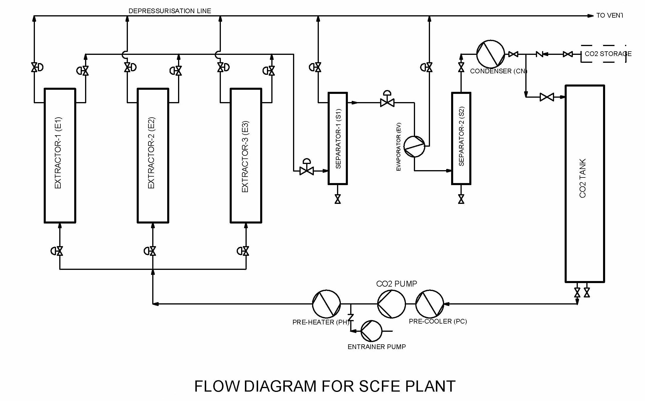
The commercial scale SCFE plant has three extractors, two separators, one CO2 hold-up tank and heat exchangers (see enclosed flow diagram). The extraction process works in a closed loop with constant circulation of CO2 in the system. It is a semi-batch operation with typical batch time of 2 to 4 hours. CO2 is liquefied and fed to the hold-up tank through a heat exchanger (Condenser). Liquid CO2 is then fed to the high-pressure metering pump, through a heat exchanger (sub-cooler) to ensure supply of CO2 in liquid form. The high-pressure liquid from the pump discharge is then heated in a heat exchanger (pre-heater) to achieve supercritical temperature. The entrainer pump can be used for dosing a small quantity of other solvents such as water, ethanol etc. in to the CO2 stream, if desired. This supercritical fluid then flows through the extractors. The raw material powder, to be extracted is held in these extractors with help of perforated baskets for easy handling. Extractors are equipped with specially designed quick acting closures for easy and fast opening of extractors. At any given time only two extractors operate in extraction mode, while the third extractor is out of cycle for change of feed. When any of the two operating extractors need feed change, it is taken out of process and replaced by the third extractor having fresh feed. This sequencing continues to minimise the downtime required for feed change. The supercritical CO2 with dissolved extract then flows to separators.
In the separators, lower temperature and pressure conditions are maintained for recovery of the extract from the CO2 stream. Thus with proper selection of conditions, fractionation of extract can be achieved by using two separators operating in series. Separator-1 is maintained at supercritical conditions, where typically high molecular weight components of the extract precipitate. Whereas in separator-2 sub-critical conditions are maintained for complete recovery of any extract from CO2 stream. The CO2 vapour leaving separator-2 is condensed and fed back to CO2 hold-up tank.
When the solid feed in the extractor needs replacement or when plant is to be shut down, respective vessels are depressurised to atmospheric pressure. In doing so maximum possible CO2 is fed back to CO2 hold-up tank through CO2 depressurising line.